The purpose of this lab was to get a sense for how to program analog and digital input/output with an Arduino.
Examples shown to us in class
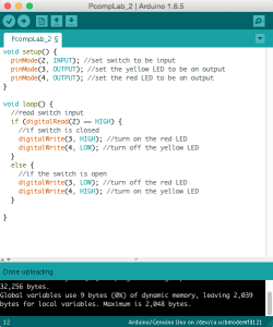
I started with the digital input example where I was able to get two different colored LEDS to alternate based on a switch button. I realized halfway through that I had switched the LEDs from what was shown in the lab but it was easy enough to change the code and have it work properly either way.
Video-Aurdino Alternating LEDs
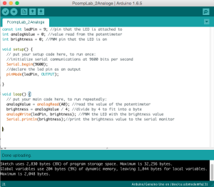
Next I worked on the analog input lab which uses a potentiometer to effect a variable as the analog input and apply a range of power to an LED via the digital output. (a portion of the previous circuit was left on the board).
Photometer
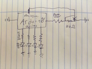
After completing these labs I decided to try to build a sort of photometer with some LEDs and a photosensor. My goal was to illuminate the LEDs in a sequence as the resistance of the photosensor changed. This meant reading an analog input and providing power to a series of LEDs via the digital out. The schematic I drew at the time looked like this:
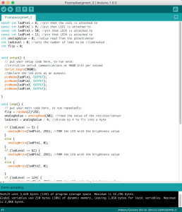
I started using a potentiometer rather than the light sensor so that I could test the programming for the lights a series of precise levels. After some trial and error with the programing I had it working roughly the way I wanted it to.
Video – Arduino Indicator Light Photometer
The LEDs turn on and off in sequence as the resistance changed and when the range was maxed out they all flickered to indicate that it was as high as possible. Lastly I removed the potentiometer and replaced it with a photosensor and a 10 kohm pull down resistor. I recalibrated some of the levels so that the LEDS would generally represent a range of typical room brightness and felt happy with the results.
Video – Arduino Indicator Light Photometer (2)


