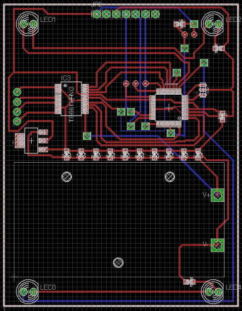
Here is a slide show covering some of the work I did in my PCB Fab class.

Here is a slide show covering some of the work I did in my PCB Fab class.

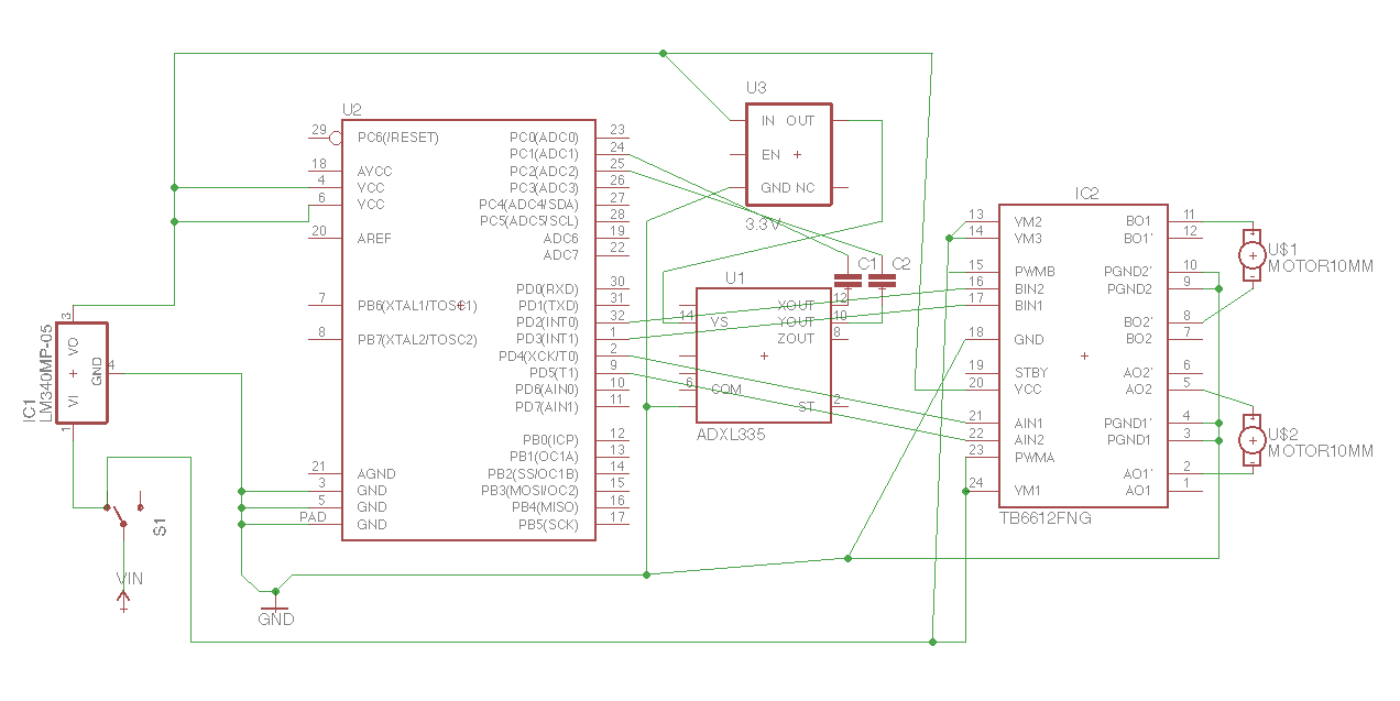
This week I made a really bad circuit schematic for a little motorized vehicle that reacts to being bumped. I expect to refine this a lot more.

The basic components here are a 9v battery, a switch, a 5v regulator, an atmel arduino uno chip, a 3v regulator, an adxl335 accelerometer, some capacitors to filter noise from the sensor, an H-Bridge and two motors.
For my PCB project I’ve decided to make maybe one of two different types of autonomous vehicles. The first one I tried out was a BEAM circuit “solar roller” that I found some instructions for here. I had some difficulty getting the circuit to work as designed but having tested the voltage of my solar panel and the motor the concept should work to create a little vehicle that nudges around a room based on the solar intensity. The other circuit I worked on was digital and responded to accelerometer input to direct a much faster burst of activity from the car. I think I would like to either make both as separate vehicles that might interact with each other or combine the circuits onto the same board and have different modes. Ideally I will encase both circuits in a 3d printed car shaped case.
Videos:
Solar Circuit (sorry for the bad orientation!) Accelerometer Circuit
The primary components for both of these vehicles include:
an Adafruit ADXL355 Accelerometer, and arduino uno, a couple of motors I pulled out of a game controller, some transistors, capacitors, resistors and diodes. I think I could improve my current design for both by controlling the direction of the car with a motor control chip or by building an H-bridge.
The code for the accelerometer based vehicle is as follows based on a spark fun accelerometer library example:
/*
ADXL3xx
Reads an Analog Devices ADXL3xx accelerometer and communicates the
acceleration to the computer. The pins used are designed to be easily
compatible with the breakout boards from Sparkfun, available from:
http://www.sparkfun.com/commerce/categories.php?c=80
http://www.arduino.cc/en/Tutorial/ADXL3xx
The circuit:
analog 0: accelerometer self test
analog 1: z-axis
analog 2: y-axis
analog 3: x-axis
analog 4: ground
analog 5: vcc
created 2 Jul 2008
by David A. Mellis
modified 30 Aug 2011
by Tom Igoe
This example code is in the public domain.
*/
const int xpin = A3; // x-axis of the accelerometer
const int ypin = A2; // y-axis
const int zpin = A1; // z-axis (only on 3-axis models)
int xaccl = 0;
int yaccl = 0;
//int zaccl = 0;
int p_xaccl = 0;
int p_yaccl = 0;
//int p_zaccl = 0;
float lightTimeXplus = 0;
float lightTimeXminus = 0;
float lightTimeY = 0;
//float lightTimeZ = 0;
void setup() {
// initialize the serial communications:
Serial.begin(9600);
pinMode(7, OUTPUT);
pinMode(6, OUTPUT);
pinMode(5, OUTPUT);
pinMode(4, OUTPUT);
}
void loop() {
xaccl = analogRead(xpin);
yaccl = analogRead(ypin);
//zaccl = analogRead(zpin);
// print the sensor values:
Serial.print(analogRead(xpin));
// print a tab between values:
Serial.print(“\t”);
Serial.print(analogRead(ypin));
// print a tab between values:
//Serial.print(“\t”);
//Serial.print(analogRead(zpin));
Serial.println();
if (xaccl > p_xaccl + 5 && millis() > 2000) {
digitalWrite(7, HIGH);
lightTimeXplus = millis();
delay(500);
} else if (xaccl < p_xaccl – 5 && millis() > 2000) {
digitalWrite(6, HIGH);
lightTimeXminus = millis();
delay(500);
}
if (millis() – lightTimeXplus > 5000) {
digitalWrite(7, LOW);
}
if (millis() – lightTimeXminus > 5000) {
digitalWrite(6, LOW);
}
p_xaccl = analogRead(xpin);
p_yaccl = analogRead(ypin);
// p_zaccl = analogRead(zpin);
}